Find attached ORIGINAL DOCUMENT for complete project documentation.
Abstract
This project aimed to develop an assistive device for the visually impaired by utilizing image classification, proximity detection, and haptic feedback mechanisms. The device aimed to enhance the independence and safety of visually impaired individuals by providing real-time audio feedback of recognized objects and proximity alerts to detect nearby obstacles, specifically focusing on recognizing people and cars. The developed device successfully recognizes people and cars with a 0.9 accuracy, when powered with a large current source, due to current constraints, initial testing with a 9v battery proved challenging but later testing will be conducted. Additionally, the proximity alert system effectively detects obstacles and alerts the user through vibration feedback. One recommendation to improve the device would be to have an optimal current supply source and should be portable and light.
1. Introduction
1.1 Overview
This chapter will cover the background information on how technology has been applied to help come up with devices that can be used by the blind, the problem facing the blind community, solution that has been proposed, objectives of the project and the block diagram of the project to be designed and constructed.
1.2 Background Information
In a recent conducted by world health organization, it is estimated that a total of 49 million people is blind worldwide (World Health Organization, 2020). The affected have their autonomy jeopardized in terms of many everyday tasks, with the emphasis being placed on those that involve moving through an unknown environment.
Generally, people rely on sight to know their location in an environment and what is around them. This has shown that sight is an important part of daily navigation of unfamiliar and familiar environment. As for the blind community, lack of visual data has resulted to them relying on other means such as echolocation to navigate in an unfamiliar environment. Recent research conducted on blind people brain scans has found that when they use echolocation in lieu of sight, they’re actually using the visual cortex, the region of the brain that processes sensory information from our eyes (Thaler, Arnott, & Goodale, 2011) This has resulted to various research conducted to find ways to assist blind people to navigate in their environment. One example is the white cane which has become a symbol for the blind community. It helps them navigate in unfamiliar environment without having to worry about relying on means such as echolocation which might be a challenge in the open air. Though the white cane has been popular over the decades, it has still it’s limitations, such as unable to differentiate different obstacles and also limited range.
1.2.1 Electronic travel aids (ETAs)
Recent advances in technology have led to development of assistive devices for the blind. The use of assistive devices has been increasing, and several electronic aid devices have been introduced over the past few years, called electronic travel aids (ETAs). ETAs have been combining various aspects of technology to come up with devices that are user friendly and easy to use. This has resulted to using sensors such as Lidar and ultrasonic sensor to provide distance information to the person.
These technologies have been relying on the various types of sensors to pick the required signals thus have some limitations. An example is when the white cane is fitted with an ultrasonic sensor, it will be limited to only objects that can reflect back the ultrasonic sound wave and has limited range. Research has been conducted by various institutions to see how computer vision technology used in self-driving cars and in robotics such as Boston Dynamic’s robot dog called Spot (Boston Dynamics, 2023) can be used as a guiding tool for the blind. They rely on vision from cameras, distance data from Lidar and an AI to be able to interpret what’s being fed by the camera to useful data that can be fed to the cars control system to perform the necessary action such as obstacle avoidance.
By applying the same concept, ETAs are being developed that are more capable compared to the one used earlier on.
1.2.2 Artificial intelligence
In 1956, John McCarthy coined the term artificial intelligence (Mintz & Brodie, 2019) He defined AI as the ability of a machine to emulate human behavior and perform tasks without human intervention. This involves using simple models created by writing simple programs to complex programs that are able to perform different tasks with minimal programming from a person which commonly use machine learning algorithms.
Advancement in the field of AI has led to researchers coming up with advanced models that are able to classify objects to various categories. These recent developments have led to innovative ideas such robots that can be able to identify various objects and detect anomalies such as a self-driving car will be able to classify a pedestrian crossing the road and be able to stop without relying on traffic lights or any other road sign.
The exponential growth of this field has led to development of algorithms such as YOLO which are able to classify multiple objects at the same time and can be used in many areas that requires object detection, such as creating a navigation system for the blind.
YOLO algorithm has become popular due to its large broad data classification and easy to use in a project. The below image shows one project created by Juan Cruz Martinez that shows how such an algorithm will classify various objects in a given frame (Martinez, 2021)
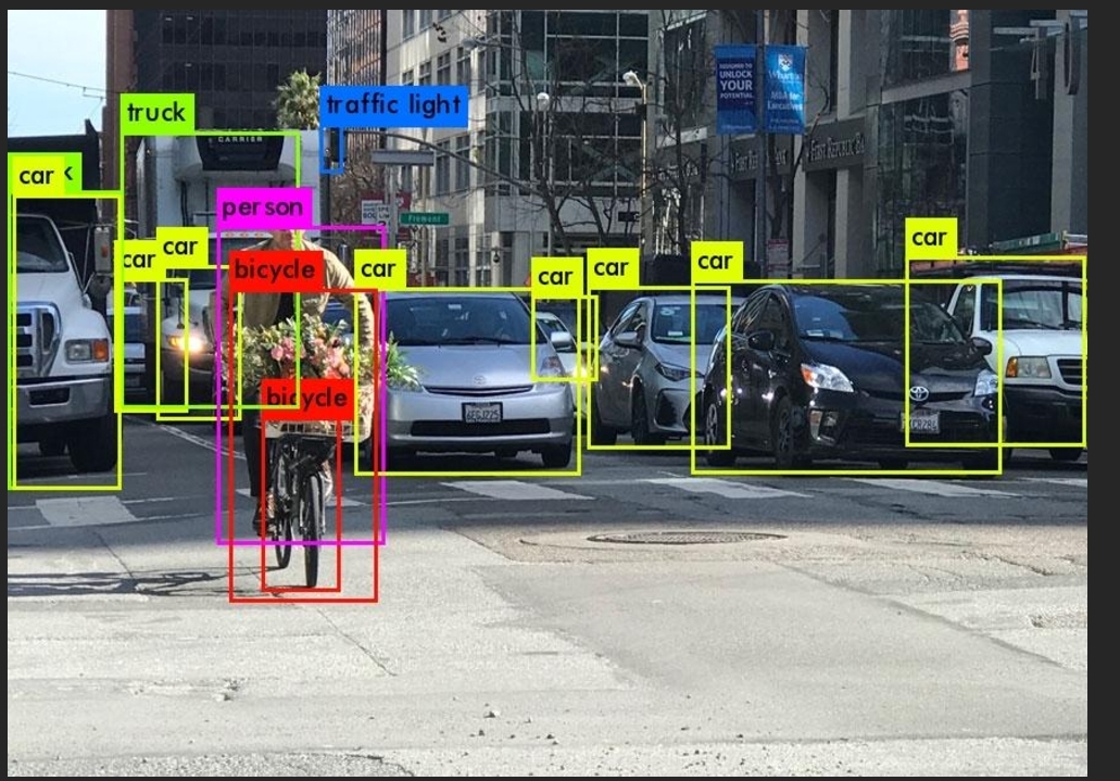
The above image shows clearly the different objects detected in the picture and labelled as per what they are. It can be seen that the algorithm is able to pick up various cars, bicycle, traffic light and person in the captured frame. This information can later be processed to work in various projects such as in self-driving cars which, as mentioned above, requires constant update of what’s around them. By this approach, the same algorithm can be used in development of ETAs. But this poses a challenge in which YOLO algorithm requires a machine with enough processing capabilities and ETAs are supposed to be light and portable to be comfortable, thus a light algorithm for object recognition will be required which will be discussed in the next chapter.
1.3 Problem Statement
Human and vehicle traffic is a major factor found in every busy area, be it part of a city or inside a school premise. This can be a challenge for a blind person to navigate through the crowd as he or she will depend on the person ahead seeing him and letting him pass, otherwise, collision might be imminent.
In a pedestrian busy pathway, it’s quite challenging, even for a person who can see, to walk properly when there is a person in front of them walking at a slower pace than they are. This can be a big challenge to a blind person as he or she will not be able to tell if the distance between him and the person in in front is reducing thus can lead to him or her tripping over.
1.4 Proposed Solution
In order to curb the above stated problems, an AI will be used to be able to detect and recognize cars and people present right at the front of the blind person by using a trained algorithm. The algorithm will be able to detect a person or/and a car captured by the camera and recognize accordingly. This will be combined with a proximity system that will provide an alert system by calculating the distance and determining whether collision is imminent by comparing distance measurements taken at a given time interval. The alert system will be informed if audio feedback informing the wearer action to take and a vibration motor that will act as a supplement Incase collision is too close.
1.5 Objectives
The following were the objectives that guided the implementation of the proposed device.
1.5.1 Main Objective
To design, construct, program and test of an AI Assisted navigation device.
1.5.2 Specific objectives
i. To train, test and deploy a person and car recognition model.
ii. To design, construct, test and interface the audio amplifier.
iii. To design, construct and test a constant 5V power supply system.
1.5 Block Diagram

2. Related work
In the realm of assistive technologies for the visually impaired, various navigation systems have been developed to enhance mobility. Mounir Bousbia-Salah pioneered a system utilizing three ultrasonic sensors – two strategically positioned on the user’s shoulders and one integrated into the white cane (Bousbia-Salah, Maamar, & Larbi, 2011). This innovative design enabled real-time object detection within a range of 6 meters, covering both overhanging obstacles and those at ground level. The system conveyed information to users through tactile feedback via two vibration motors and auditory cues (Bousbia-Salah, Maamar, & Larbi, 2011).
In a parallel effort, Koharwal and colleagues devised a navigation system featuring a Raspberry Pi running an object recognition algorithm based on OpenCV. This system utilized IR sensors to map object shapes and sizes, while ultrasonic sensors provided distance information. The culmination of these inputs was converted into audible feedback for the user through headphones (Koharwal, Awwad, & Vyakaranam, 2019).
Building upon these foundations, the system in this project document introduces notable improvements. Firstly, a recognition model based on Convolutional Neural Networks (CNN) is employed, quantized to below 500KB. This reduction in computational requirements facilitates implementation on various microcontrollers, expanding the accessibility and deployment potential of the navigation system. Additionally, by using a cheap controller, the cost is reduced drastically while improving performance by using a neural network.
3. Project Design
3.1 Software Design
This involved designing the software that will run the entire system, from the neural network to the device software that will assist in coordinating the various sensors and output devices. The convolution neural network was developed on Google colab and the system software was developed using Arduino ide.
3.2 Design of the convolution neural network.
Designing an effective CNN requires the following to be observed:
- Type of dataset to be used
- Architecture of the model
- Deployment
- Data preprocessing
In this project, the underlying problem is to recognize two classes of images to their respective classes. This will involve preprocessing the data to the required format that can be fed through an input layer of the neural network. The dataset was prepared in a folder named ‘dataset’ with subfolders for various classes, for the case of this project the subfolders are ‘person’ and ‘car’.
Data preprocessing was done using opencv (a python library) to provide the required tensors that can be fed to the input of the model. As pixel value ranges from 0 – 255, dividing the tensors with 255 provided a normalized training data of range 0 to 1.
Normalized tensor = tensor/255
training_data = []

def create_training_data ():
    for category in CATEGORIES:
        path = os.path.join (DATADIR, category)
        class_num = CATEGORIES.index (category)
        for img in os.listdir (path):
            try:
                img_array = cv2.imread (os.path.join(path, img),cv2.IMREAD_GRAYSCALE)
                new_array = cv2.resize (img_array, (IMG_SIZE, IMG_SIZE))
                new_array = new_array/255
                training_data.append ([new_array, class_num])
            except Exception as e:
                pass

create_training_data ()
Data augmentation was performed on the preprocessed data to virtually increase the size of the data in order to mitigate overfitting. The following steps will be carried out during data augmentation:
- Rotation range: This determines degree for random rotations. Random range = 20
- width shift range and height shift range: Determines random horizontal and vertical shifts, respectively, as a fraction of the total width or height. width shift range = 0.15 and height shift range = 0.2
- shear range: Shear intensity, for giving a diagonal shape to the images. It’s a specified angle in degrees. Shear range = 0.2
- zoom range: Range for random zoom. Zoom range = 0.3
- horizontal flip: Boolean, indicating whether to randomly flip images horizontally. Set to True
- Fill mode: Filling in newly created pixels after a rotation or a shift. Set to ‘nearest’
from tensorflow.keras.preprocessing.image import ImageDataGenerator

datagen = ImageDataGenerator(
    rotation_range=20,
    width_shift_range=0.15,
    height_shift_range=0.2,
    shear_range=0.2,
    zoom_range=0.3,
    horizontal_flip=True,
    fill_mode='nearest'
)
3.2.1 Convolution neural network architecture design
A Convolutional Neural Network architecture was designed for image classification. It begins with a convolutional layer having 64 filters with a size of (3, 3), implementing L1 regularization. This was followed by a rectified linear unit (ReLU) activation function to introduce non-linearity. A max-pooling layer with a pool size of (2, 2) reduces spatial dimensions. A dropout layer helps prevent overfitting by randomly deactivating 20% of neurons. The architecture continued with a second convolutional layer featuring 64 filters and a similar structure of activation, pooling, and dropout. Subsequently, a flatten layer transformed the 2D feature map into a 1D vector, and a dense layer with 32 neurons follows, applying ReLU activation.
The final dense layer with 2 neurons and a softmax activation function is utilized for binary classification.
import tensorflow as tf
from tensorflow.keras.models import Sequential
from tensorflow.keras.optimizers import Adam
from tensorflow.keras.callbacks import ModelCheckpoint
from tensorflow.keras.layers import Dense, Flatten, Conv2D, MaxPooling2D, Dropout, Activation
from tensorflow.keras import regularizers
from sklearn.model_selection import train_test_split

l_r = 0.0001
Epochs = 15
opt = Adam(learning_rate = l_r)
batch_size = 32

X_train, X_val, y_train, y_val = train_test_split(X, y, test_size=0.2, random_state=42)
model = Sequential()

model.add(Conv2D(64, (3, 3), input_shape=X.shape[1:],kernel_regularizer=regularizers.l1(0.01)))
model.add(Activation("relu"))
model.add(MaxPooling2D(pool_size=(2, 2)))
model.add(Dropout(0.2))

model.add(Conv2D(64, (3,3)))
model.add(Activation("relu"))
model.add(MaxPooling2D(pool_size = (2,2)))
model.add(Dropout(0.1))

model.add(Flatten())
model.add(Dense(32))
model.add(Activation("relu"))

model.add(Dense(2))
model.add(Activation ("softmax"))


model.compile(loss = "binary_crossentropy",
              optimizer = opt,
              metrics = ["accuracy"])

datagen.fit(X_train)

train_generator = datagen.flow(X_train, y_train, batch_size = batch_size)

#print(type(train_generator))

history = model.fit(train_generator, steps_per_epoch=len(X_train) // batch_size, epochs=Epochs, validation_data=(X_val, y_val))

#checkpoint = ModelCheckpoint(save_path,save_freq = 'epoch', monitor='val_loss', save_best_only=True, save_weights_only=False, mode='auto')
#history = model.fit(X,y, batch_size = 32, epochs = Epochs, verbose = 1, callbacks = [checkpoint])
3.2.2 Feature extraction
Image size = 96 × 96
First Convolutional Layer:
Number of filters = 128
Filter size = (3, 3)
Stride is 1 and padding is ‘same’, the output size would remain 96x96.
Number of features = 128× (96× 96)=1179648
First MaxPooling Layer:
Pool size = (2, 2)
The pooling layer halves the spatial dimensions.
Output size = 48x48 (features remain the same;1179648)
First Dropout Layer:
No change in the number of features.
Second Convolutional Layer:
Number of filters = 64
Filter size = (3, 3)
Using the same stride and padding, the output size would be 48x48.
Number of features = 64× (48× 48) =147456
Second MaxPooling Layer:
Pool size = (2, 2)
Halving the spatial dimensions again.
Output size = 24x24 (features remain the same;147456 )
Second Dropout Layer:
No change in the number of features.
Flatten Layer:
Flatten converts the 8x8 feature map to a 1D vector.
Number of features = 24× 24 =576
First Dense Layer:
Number of neurons = 64
Second Dense Layer (output layer for binary classification):
Number of neurons = 2
3.2.3 Model conversion and deployment
After the training process was completed and the best model was obtained, conversion was carried out to a Tensorflow lite model that was later deployed using edge impulse api to an arduino compatible library. This ensured seamless integration to esp32 microcontroller.
3.2.3.1 Tflite conversion:
import tensorflow as tf

DATADIR = data_path
CATEGORIES = ['person', 'car']
IMG_SIZE = 50

def representative_data_gen():
    data_dir = DATADIR
    batch_size = 32
    img_height = IMG_SIZE
    img_width = IMG_SIZE

    class_names = CATEGORIES

    train_images = tf.keras.preprocessing.image_dataset_from_directory(
        data_dir,
        class_names=class_names,
        validation_split=0.2,
        subset="training",
        seed=123,
        image_size=(img_height, img_width),
        batch_size=batch_size)

    #standardize the images
    normalization_layer = tf.keras.layers.experimental.preprocessing.Rescaling(1/255)
    normalized_ds = train_images.map(lambda x, y: (normalization_layer(x), y))
    image_batch, labels_batch = next((iter(normalized_ds)))
    first_image = image_batch[0]
    #print(image_batch)

    print(np.min(first_image), np.max(first_image))

    for input_value in tf.data.Dataset.from_tensor_slices(image_batch).batch(1).take(100):
        print(input_value.shape)
        # Model has only one input so each data point has one element.
        yield [tf.constant(input_value, dtype=tf.float32, shape=(1, img_height, img_width, 1))]

representative_data_gen()

converter = tf.lite.TFLiteConverter.from_keras_model(model)
converter.optimizations = [tf.lite.Optimize.DEFAULT]
converter.representative_dataset = representative_data_gen
converter.target_spec.supported_ops = [tf.lite.OpsSet.TFLITE_BUILTINS_INT8]
converter.inference_input_type = tf.uint8
converter.inference_output_type = tf.uint8
tflite_quant_model = converter.convert()
3.2.3.2 Edge impulse deployment
import edgeimpulse as ei
from google.colab import userdata

API_KEY = userdata.get('EI_API_KEY')

ei.API_KEY = API_KEY

ei.model.deploy(model=tflite_model,
                model_input_type=ei.model.input_type.OtherInput(),
                model_output_type=ei.model.output_type.Classification(),
                output_directory=Lib_folder)
3.3 system flowchart

4. Results
The results are available on the project document hosted on GitHub. The below images are taken from the project document. Kindly refer to the original document for detailed results.
4.1 model summary
model.summary ()

4.2 Training curve
import matplotlib.pyplot as plt

plt.plot(history.history['accuracy'], label='accuracy')
plt.plot(history.history['val_accuracy'], label='val_accuracy')
plt.plot(history.history['loss'], label='loss')
plt.plot(history.history['val_loss'], label='val_loss')
plt.xlabel('Epoch')
plt.ylabel('Metric Value')
plt.legend()
plt.show()

4.3 Edge impulse summary
Overall accuracy of 0.86 was achieved after conversion to tflite model.

4.3 Object detection usage
The below code runs every frame captured through the model and plays respective audio on object detection.
// Function to play audio on detection
void playAudio(const unsigned char* audioArray) {
    unsigned int audioLength = 35884;
    for (unsigned int i = 44; i < audioLength; i++) {
        uint8_t sample = pgm_read_byte(&audioArray[i]);
        analogWrite(SpeakerPin,sample);
        delayMicroseconds(1000000 / sampleRate);
  }
}

// object detection usage
#if EI_CLASSIFIER_OBJECT_DETECTION == 1
    bool bb_found = result.bounding_boxes[0].value > 0;
    for (size_t ix = 0; ix < result.bounding_boxes_count; ix++) {
        auto bb = result.bounding_boxes[ix];
        if (bb.value == 0) {
            continue;
        }
              ei_printf("    %s (%f) [ x: %u, y: %u, width: %u, height: %u ]\n", bb.label, bb.value, bb.x, bb.y, bb.width, bb.height);
        if (bb.label == "person" && bb.value  >= 0.8){
            playAudio(person_wav);
            ei_delay(2000)
        }
        else if (bb.label == "car" && bb.value >= 0.8){
            playAudio(car_wav);
            ei_delay(2000);
        }
    }
    if (!bb_found) {
        ei_printf("    No objects found\n");
    }
#else
    for (size_t ix = 0; ix < EI_CLASSIFIER_LABEL_COUNT; ix++) {
        ei_printf("    %s: %.5f\n", result.classification[ix].label,result.classification[ix].value);
    }
#endif
5 CONCLUSION AND RECOMMENDATION
5.1 Overview
This chapters covers the summary of the entire project, what was achieved, challenges encountered during design, implementation and testing and recommendations.
5.2 Statement of initial objectives
The main objective was to design a machine learning model that would be able to classify images of people and car, and run locally on the microcontroller. This was achieved and the model had a 0.9 validation accuracy, which was within the expected range. Converting the model to Arduino library dropped the accuracy to 0.85, which was within the expected range. On running the model locally, inferencing time was 500ms to 700ms which was near real time.
The secondary objectives were to power the device with a constant 5v portable power supply and to design an audio system. The voltage regulation worked and provided a constant 5v. The audio system proved challenging as there were no compatible libraries to work with it as discussed in the previous chapter. Testing on the new code had elements of audible high frequency tones that cancelled out the expected voice.
5.3 Summary of achievements
Upon implementing the circuit and the program, image classification was successful but displaying the results was only possible on a serial monitor as audio playing was not possible as per the time of this report.
5.4Applications of the system
With improvement to the audio, the system can be used to help the blind navigate areas with high traffic of both people and cars. This can limit injuries that can occur from collision.
Further improvement of the model can be made to have a wide range of objects detected thus useful in day to day applications.
5.5 Benefits of the study
This project covered a wide range of study, thus enabled us to learn. Some of the concepts we learnt were on machine learning and how neural networks are designed. We designed a convolution neural network, this helping us understand concepts involved in deep learning. Working with audio also helped us understand how sampling affects different audio formats and how to dump any audio to it’s respective digital bits. By conducting this study, we were able to learn how concepts we learnt in previous school units are used to develop circuits in the real world.
5.6 Challenges faced during design and implementation
This project was conducted mostly using Google colab, which at times the GPUs were not a available thus training speed was limited by the CPU.
Another challenge faced was lack of compatible audio library this resulting to using pwm to play the audio. This resulted in loss of quality of the expected audio.
5.7 Recommendations
In order to improve the device, some of the recommendations that can be done are:
• Finding a way to have Audio without relying on pwm.
• Improving the voltage supply circuit to have sufficient voltage and avoid the stated voltage drops.
• Using a stronger tactile feedback mechanism rather than relying on Piezoelectric Vibrator.
5.8 Conclusion
In conclusion, the device that was proposed in this project was implemented and constructed. The main objective being to be able to detect people and cars was achieved by use of CNN model. This model was ported to a lite format that was converted to arduino compatible library, which was later uploaded to the device. Inferencing worked as expected with a 0.9 accuracy. Audio playback was not possible as per the time of this report but fixes are being worked on.
References
- Albawi, S., Mohammed, T. A., & Al-Zawi, S. (2017, August). Understanding of a convolutional neural network. In 2017 international conference on engineering and technology (ICET) (pp. 1-6). Ieee.
- Boston Dynamics. (2023, November 16). Boston dynamics. Retrieved from Spot Boston dynamics: https://bostondynamics.com/products/spot/ [Accessed 12th November, 2023]
- Bousbia-Salah, M., Maamar, B., & Larbi, A. (2011). A navigation aid for blind people. Journal of Intelligent & Robotics Systems, 64, 387 - 400.
- El Naqa, I., & Murphy, M. J. (2015). What is machine learning? . Springler, 3-11.
- Hymel, S. B., Situnayake, D., Elium, A. W., Kelcey, M., & Reddi, V. J. (2022). Edge Impulse: An MLOps Platform for Tiny Machine Learning. arXiv preprint arXiv.03332.
- Ketkar, N., & Moolayil, J. (2021). Convolutional neural networks. Deep Learning with Python. Learn Best Practices of Deep Learning Models with PyTorch, 197-242.
- Koharwal, S., Awwad, S. B., & Vyakaranam, A. (2019). Navigation system for blind - Third eye. International Journal of Innovative Technology And Exploring Engineering, 1086-1092.
- Lin, J., Zhu, W. M., Wang, W.-C., Gan, C., & Han, S. (n.d). On-Device Training Under 256KB Memory. MIT-IBM Watson AI Lab.
- Mahesh, B. (2020). Machine learning algorithms-a review. . International Journal of Science and Research (IJSR), 381-386.
- Martinez, J. C. (2021, march 15). Infotech. Retrieved from infotech.report: https://infotech.report/guest-articles/real-time-object-detection-in-video-with-intro-to-yolo-v3[Accessed 12th , November 2023]
- Mintz, Y., & Brodie, R. (2019). Mintz, Y., Introduction to artificial intelligence in medicine. Minimally Invasive Therapy & Allied Technologies.
- Thaler, L., Arnott, S. R., & Goodale, M. A. (2011). Thaler, L., ArnoNeural correlates of natural human echolocation in early and late blind echolocation experts.
- Torrey, L., & Shavlik, J. (2010). Transfer learning. In Handbook of research on machine learning applications and trends: algorithms, methods, and techniques. IGI global., 242-264.
- Warden, P., & Situnayake, D. (2019). Tinyml: Machine learning with tensorflow lite on arduino and ultra-low-power microcontrollers. O'Reilly Media.
- World Health Organization. (2020, october 9). World health organization. Retrieved from who: https://www.who.int/news/item/09-10-2003-up-to-45-million-blind-people-globally---and-growing#:~:text=Globally%2C%20an%20estimated%2040%20to,2020%3A%20The%20Right%20to%20Sight. [Accessed 8th November, 2023]